Origins
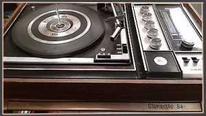
Several years ago, I reluctantly accepted a free, nonfunctioning vintage record player – a Realistic Clarinette 84, produced between 1977 to 1981. At the time, I saw it as just taking up space, but it outwardly appeared in good condition so I kept it around.
It sat for several months before I came up with a way to re-purpose it. I decided to turn it into a MIDI controller, using the control inputs and an Arduino to dynamically create music and send it out as MIDI. It took a while to get around to it, but I wired the knobs and switches to an Arduino, added an LCD screen and a MIDI jack. Then, having never used a MIDI keyboard or anything else, I struggled a bit with finding the best way to turn the MIDI into sound waves. I ordered an obsolete MIDI-USB cable and had driver issues. Then life happened; I dropped the project for a while, and then disassembled and cannibalized the parts for some other project. The record player sat for another three years and moved a couple of times with me.
Revival
During that time however, the Raspberry Pi came out and hardware became cheaper. I decided it was time to dust off the old project and finally finish it. I acquired a Pi model B with the Wolfson/Cirrus sound card. I decided to use an Arduino Uno for the input/output (I/O) and the Pi to create actual audio, skipping the whole MIDI part. The first design failed. Even running with a real-time kernel, the Pi couldn’t keep up. The notes lagged and the timing was off – bad. I’m using a Python module to communicate to the Sonic-Pi server, running without the GUI (headless). So I’m doing something inefficient (Python, Ruby, Sonic-Pi) as efficiently as I can. To make the Pi B work, I’d probably have to write something in C and talk to scsynth directly. Not only that, but the Uno didn’t have enough I/O points to hook up all the controls. At first I didn’t care; a few knobs and couple switches would be enough to play with. But then, a good design doesn’t have dummy controls.
Assembly
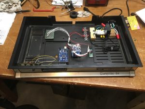
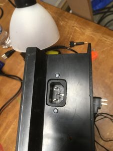
Here it is in the early stage of assembly. I wound up rearranging nearly everything. I chose to use a common IEC C14 jack for the power.
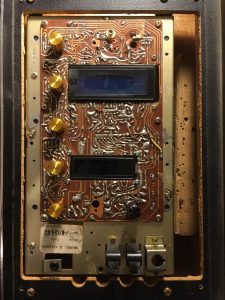
I upgraded to Pi3 and Arduino Mega. The Arduino reads in controls and drives two LCD screens, while the Pi uses the inputs to algorithmically make music; kind of like these CCRMA projects. There are 5 knobs, a rotary encoder, three 3-position switches, two 2-position switches, and a button. I removed the plastic face plate and replaced the original knobs with gold ones. Now it has a cooler, more stripped down look.
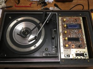
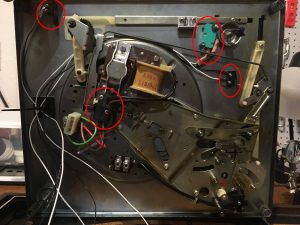
The switches around the turntable are mechanical, so I had to add micro switches on the bottom side to read their positions. There was one electric switch near the center so I just incorporated it. Here also are the shiny new gold knobs, the LCDs and the rotary encoder.
Power
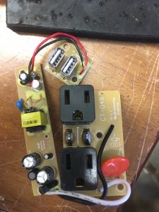
Next I wanted to move the 115VAC away from the vent slots on the bottom of the case so the high voltage components were better protected. I also needed to add a third outlet, either AC or USB, to power the Pi. Things started getting a little cramped here and it took some trial-and-error to get the components in without interfering with the fit of the top half. I’m happy with the end result, although getting there was more work than it should have been. The first outlet I tried did not fit both wall warts and the USB, so I purchased a surge projector plug-in type outlet, took it apart, and rearranged the 3 circuit boards inside so nothing contacted the top half of the record player when installed. This is basically a hack but now it’s already done and it works. I decided to leave good enough alone here and move on.
This is the outlet I used, disassembled.

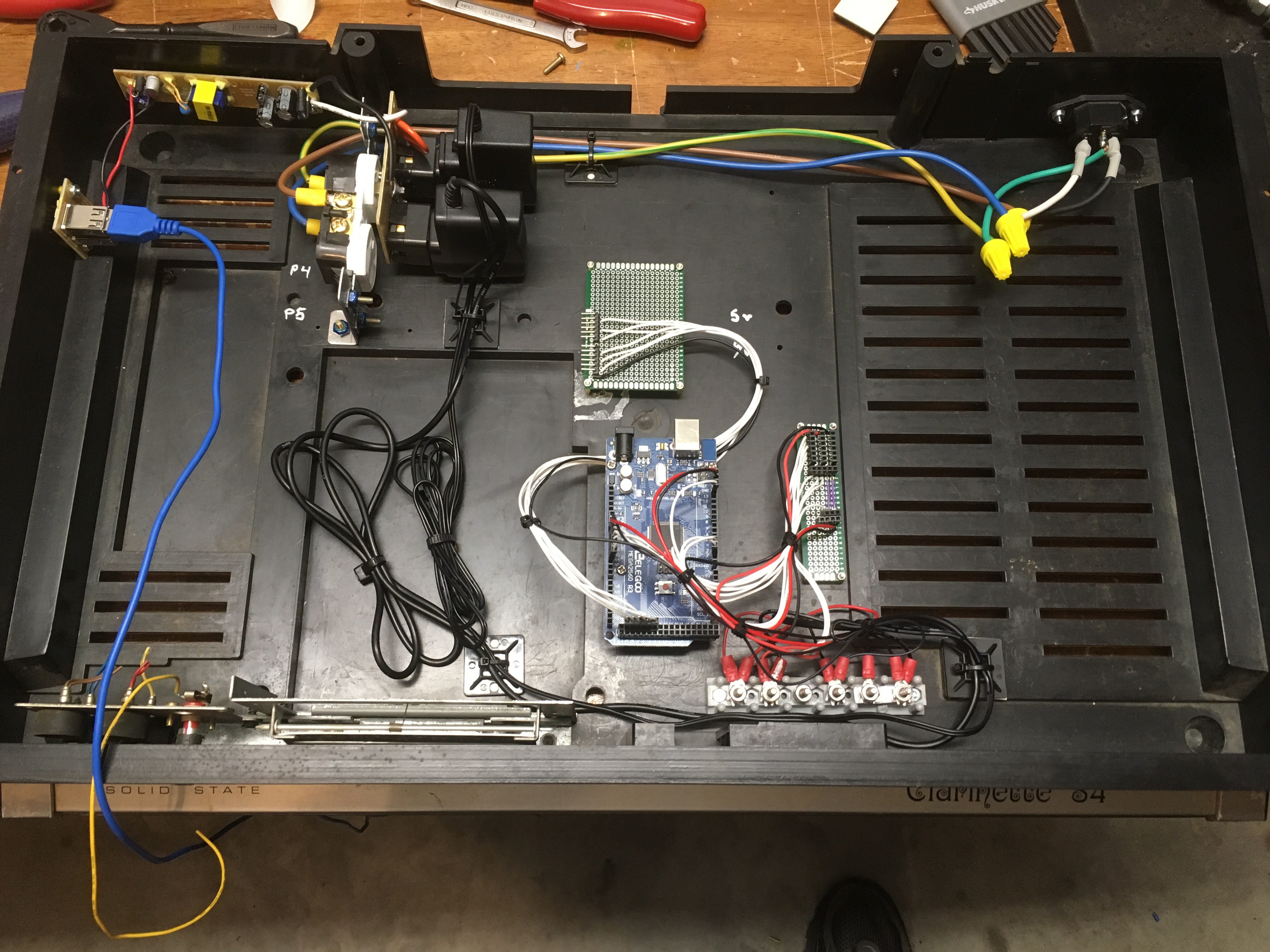
Below are the internals of the bottom half with the Arduino and power installed. The two boards adjacent to the Arduino are for the LCD and I/O signal and power distribution. This is the bottom at about 80% complete. There wasn’t much to it, even with the power being overly complicated. I added a few more signal wires and a power switch next to the power input. The Raspberry Pi has yet to be installed.
Signals
I used the Arduino internal pull-up resistors for the digital inputs (DI). Put simply, one side of each switch is connected to ground and the other side to one of the Arduino input pins. When the switch closes, it grounds the input pin; the Arduino senses that and triggers the DI. Something that can be a little counterintuitive to newbies is that the DI reads true when the switch is open and false when it is closed so you typically want to invert the values when you read them in to the software. I also used an external 5V reference voltage for the AIs.
The blue LCD is controlled via I2C and the red one is TTL serial.
Testing
I programmed the Arduino with some simple test functions to make sure all the I/O works. It just reads in all the values and displays them on the LCDs. I tested the rotary encoder first and used that to select which switch value to display on the lower LCD, while the top LCD displays the five knob input values simultaneously
At first run everything worked pretty well, except that at some point when I was rearranging the components inside I accidentally swapped the 5VDC and 9VDC grounds on the terminal block. That caused the big LCD to blink on and off and probably jacked up the reference voltages. I identified that problem pretty quickly and fixed it.
I also hit a minor snag by not properly updating the display when the switch values changed. Again, this was a real quick fix but I mention it because at first it looked like none of the switches were working, or acting strangely. The hardware/software integration stage can be difficult because of the uncertainty about what is causing a problem. What seems to be a hardware problem can be software and vice versa. It helps to be methodical and test all of your assumptions.
I made the classic “off by one” error when reading the analog inputs (AI). I used a 5 element array to store the knob values and for testing I only displayed the first one on the LCD. Well, in the updateInput() function, I stored the values like this:
knob_values[1] = analogRead(A0);
knob_values[2] = analogRead(A1);
knob_values[3] = analogRead(A2);
knob_values[4] = analogRead(A3);
knob_values[5] = analogRead(A4);
Obviously knob_values[0] never got assigned and knob_value[5] doesn’t exist, so something in memory was being overwritten. Since I was only looking at the first AI and it was always showing 0, I thought I had a more serious problem with the circuit. Since this is such a beginner mistake, I looked past it at first. I don’t know how many times I’ve been stumped by a typo.
I like highlighting my mistakes because that is how we learn best. Learning from our own mistakes is the most effective, but learning from others’ is second best.
Demo
And here it is reading inputs.
Next…
Next I need to transmit the input values to the Raspberry Pi over USB and use those as parameters for the music generation algorithm. The software development will be covered in the next post.
